Electronics
Electrical System modeling
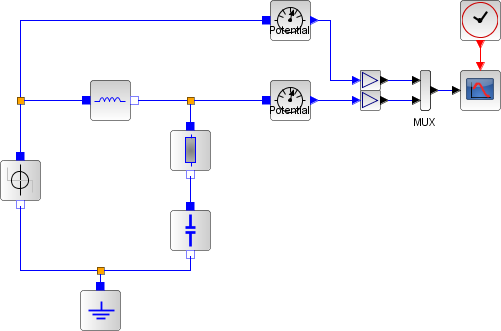
We here consider the following electrical system, with an input voltage Ue and an output voltage Ua
Mathematical modeling
In order to model the system in a mathematical way, we need to use Kirchhoff’s laws:
(1) ![]()
(2) ![]()
In addition, we need to express the mathematical function of each component:
Resistance: ![]()
Capacity: ![]()
Inductor: ![]()
Using the 2 mathematical expressions, we come to the following second order differential
equation:
![]()
Causal modeling
State-space system modeling
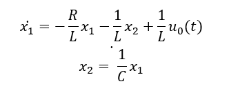
The equations for an RLC circuit are the following. They result from Kirchhoff’s voltage law and Newton’s law.

The R, L and C are the system’s resistance, inductance and capacitor.
We define the capacitor voltage Vc and the inductance current iL as the state variables X1 and X2.

thus
![]()
Rearranging these equations we get:
These equations can be put into matrix form as follows,
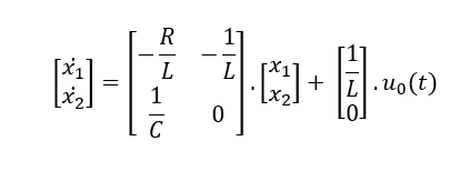
The required output equation is
![]()
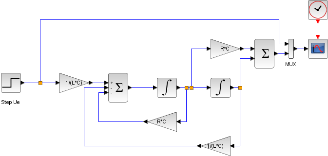
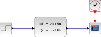
The following diagram shows these equations modeled in Xcos.
To obtain the output Vc(t) we use CLSS block from Continuous time systems Palette.
Acausal with Modelica