Modeling and simulation of a counter/timer
This article was originally published on x-engineer.org
Thanks to x-engineers for their contribution.
--
In control applications, embedded software and electronics, timers are widely used for events and time measurements. The same functionality can be obtained with a counter. From a control engineering perspective a timer and a counter are very similar but still different:
- a counter measures discrete events and works with decimal values (e.g. 10, 20, 100, etc.)
- a timer measures elapsed time and works with physical values (e.g. 0.1 s, 12 s, 35 s, etc.)
In this Xcos tutorial we are going to design and simulate a both a counter and a timer. There are different types of timers and counters, in our example we are going to focus on a start time-down implementation. This means that our timer/counter will start to process time (count) from a start value (e.g. 2 s) until it reaches 0. The start (initial) value is calibratable, which means that it can be modified by the user.
Counter – Xcos block diagram model
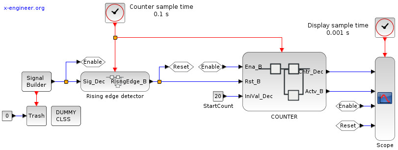
The model of the counter is enclosed in the COUNTER subsystem (user defined function). A Signal Builder is used to generate trigger signals for the counter. The outputs of the counter together with the activation signals are displayed in a Scope.
Image: Counter activation – Xcos block diagram
The counter has 3 data input signals, 2 data output signals and 1 input event (top red input). The description of the I/O is done in the table below:
| Name | Type | Description |
Ena_B |
boolean | when true (1) enables the counter, when false (0) sets the counter output to 0 |
Rst_B |
boolean | when true (1) resets the value of the counter to the initial value |
IniVal_Dec |
decimal | initial (start) value of the counter |
Cntr_Dec |
decimal | counter output |
Actv_B |
boolean | set to true (1) when the counter is different than 0 |
| (no name) | event | triggers the delay block in the counter (set to 0.1 s by the Clock block) |
The Signal Builder is generating a rectangular, periodic wave form of the enable signal. A rising edge detector is used to generate the reset signal of the counter. Every time the enable signal changes state from false (0) to true (1), the reset is triggered (only for a sample time) and initializes the counter.
The parameters of the signal builder block are:
Image: Signal builder parameters
There are two sample times in the model, provided by two Clock blocks. The first one, set at 0.1 s is used to sample the rising edge detector and the counter. The second one, set at 0.001 s is used to sample the display signal in the Scope block.
The block diagram of the COUNTER subsystem is detailed below:
Image: Counter model – Xcos block diagram
The counter is designed to use Dynamic Switch blocks, which have three inputs:
u1: upper inputu2: control (middle) inputu3: lower input
The switch passes the upper input (u1) when the control criteria is met. In our case the control criteria is u2 ~= 0, which means that the control input is different than zero (0). If the control input is 0, the switch passes the lower input (u3).
The reset signal (Rst_B) has the highest priority on setting the value of the counter (Cntr_Dec). When the reset signal is true, the counter is initialized with the start value (IniVal_Dec). When the reset signal if false, the value of the counter is decided by the enable signal (Ena_B).
When the enable signal is false, the counter is set to 0. When the enable signal is true, the current value of the counter depends on its previous value (z-1). As long as the previous value of the counter is higher than 0, we subtract 1 from it at each sample time (0.1 s), otherwise we keep it to 0.
The Delay block (1/z), sampled at 0.1 s, keeps the value of the counter fixed for 0.1 s.
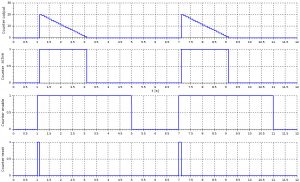
The first simulation is set to run for 12 s, with the initial value of the counter set at 20.
Image: Counter plot – 20 counts
How the counter works is self explanatory. When the enable signal (Ena_B) is set to true, the rising edge is detected (Rst_B) and the counter is initialized with 20. Further, it counts down until it reaches 0. As long as the counter counts (Cntr_Dec), the activate signal (Actv_B) is true.
The same behavior is obtained with a different initial value, 30.
Image: Counter plot – 30 counts
Timer – Xcos block diagram mode
The same principle applies also when designing a timer. The model of the timer is enclosed in the TIMERsubsystem (user defined function). We use the same Signal Builder to generate trigger signals for the timer. The outputs of the timer together with the activation signals are displayed in a Scope block.
Image: Timer activation – Xcos block diagram
The timer has 4 data input signals, 2 data output signals and 1 input event. The description of the I/O is done in the table below:
| Name | Type | Description |
Ena_B |
boolean | when true (1) enables the timer, when false (0) sets the timer output to 0 |
Rst_B |
boolean | when true (1) resets the value of the timer to the initial value |
IniVal_s |
time [s] | initial (start) value of the timer |
dT_s |
time [s] | sample time (must be equal with the event sample time) |
Tmr_s |
time [s] | timer output |
Actv_B |
boolean | set to true (1) when the timer is different than 0 |
| (no name) | event | triggers the delay block in the timer (set to 0.1 s by the Clock block) |
The same Signal Builder is used to generate a rectangular, periodic wave form of the enable signal. A rising edge detector is used to generate the reset signal of the timer. Every time the enable signal changes state from false (0) to true (1), the reset is triggered (only for a sample time) and initializes the timer. The parameters of the signal builder are the same as in the counter example.
There are also two sample times in the timer model, provided by two Clock blocks. The first one, set at 0.1 s is used to sample the rising edge detector and the timer. The second one, set at 0.001 s is used to sample the display signal in the Scope block.
The block diagram of the TIMER subsystem is detailed below:
Image: Timer model – Xcos block diagram
The functionality of the timer is very similar with the one of the counter, the only difference being that the initial value (IniVal_s) is time based and the subtracting is done with sample times (dT_s) instead of ones (1).
The first simulation is set to run for 12 s, with the initial value of the timer set at 3 s.
Image: Timer plot – 3 seconds
The timer is initialized with 3 s and keeps counting douwn until it reaches zero (0 s). The second simulation is going to initialize the timer at 4.7 s.
Image: Timer plot – 4.7 seconds
Observe that when the enable signal goes to false, the timer is interrupted and set to 0. Depending on the application, the enable signal can be set to a constant 1 (all the time enabled) and the timer reset only when it needs to measure a certain amount of time.
The same model can be used under different sample time conditions, the only requirement being to align the event sample time with the sample time parameter (dT_s).


