Human in the Loop testing
The Evolution of Aeronautics
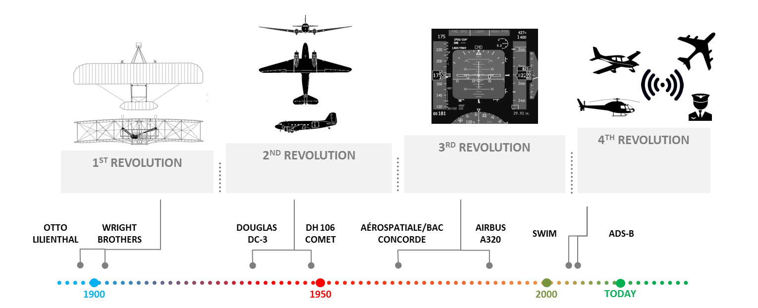
After realizing far reaching automation levels on aircraft, the aeronautics is on the cusp of the 4th revolution, the “smart” and “connected” flight!
- 1st: heavier-than-air (not zeppelins/balloons)
- 2nd: hydraulic actuators / electric drives / metal aircraft -> beginning of automation
- 3rd: glass cockpits and digital flight systems
ADS-B: Automatic Dependent Surveillance – Broadcast
Challenge
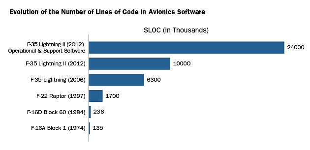
Increasing complexity
New methodologies and approaches are crucial to increase product performance and boost productivity in development, while also maintaining safety levels.
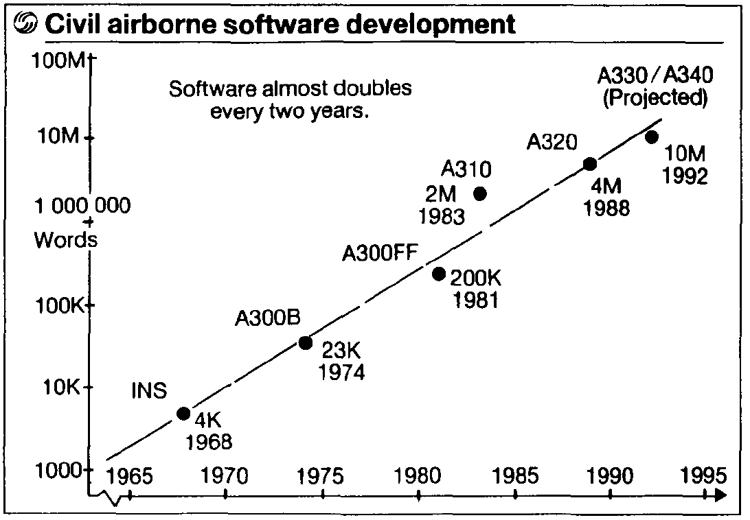
J. P. Potocki De Montalk, "Computer software in civil aircraft," Computer Assurance, 1991. COMPASS '91, Systems Integrity, Software Safety and Process Security. Proceedings of the Sixth Annual Conference on, Gaithersburg, MD, 1991, pp. 10-16.
Trend in Avionic Systems – recent research projects
2012 - EADS Innovation Works: utilization of multi-core systems in partitioned environments
2013 – CASSIDIAN: application of multi-core architectures for a degraded vision landing system for a helicopter
2014 – THALES: design principles of predictable and efficient multi-core systems to meet embedded computer requirements in avionics
2014 - Saab Aeronautics: guaranteeing determinism for avionic applications running on multiple cores and interacting through shared memory
All efforts concentrate on the applicability regarding the safety constraints of the avionics domain.
- There is no reported effort that attacks the development methodology for avionics application using multi-core architectures.
… how to boost productivity on development?
Solution
How can we apply modeling and simulation based approaches for multi-core systems?
Example Case
Terrain Awareness and Warning System
A TAWS is a flight system (a supervisory controller) that creates visual and aural warnings in order to avoid Controlled Flight into the Terrain.
Basic Modes:
- Mode 1: Excessive Descent Rate
- Mode 2: Excessive Terrain Closure Rate
- Mode 3: Altitude Loss After Take-off
- Mode 4: Unsafe Terrain Clearance
- Mode 5: Excessive Deviation Below Glideslope
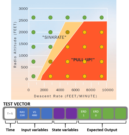
Example Mode 1: the limit altitudes (the reference being the radio altitude) are described as functions of other parameters like airspeed or rate of descent
Enhanced Features:
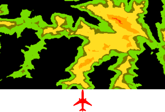
Terrain Awareness and Display (TAD) provides an image of the surrounding terrain as well as warnings and cautions regarding terrain interactions within the next 60 seconds of flight.
The terrain-based features are implemented using Scilab scripts
The digital elevation database has a resolution of 3 arc seconds (∼90 m)
- Two-phase collision detection
- Broad phase:
- Uniform grids for spatial partitioning
- Narrow Phase:
- comparison of predicted flight path with terrain elevation
- generate color coded terrain image for Navigation Display
- Broad phase:
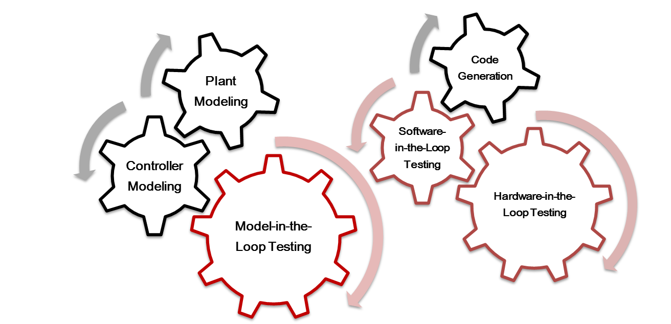
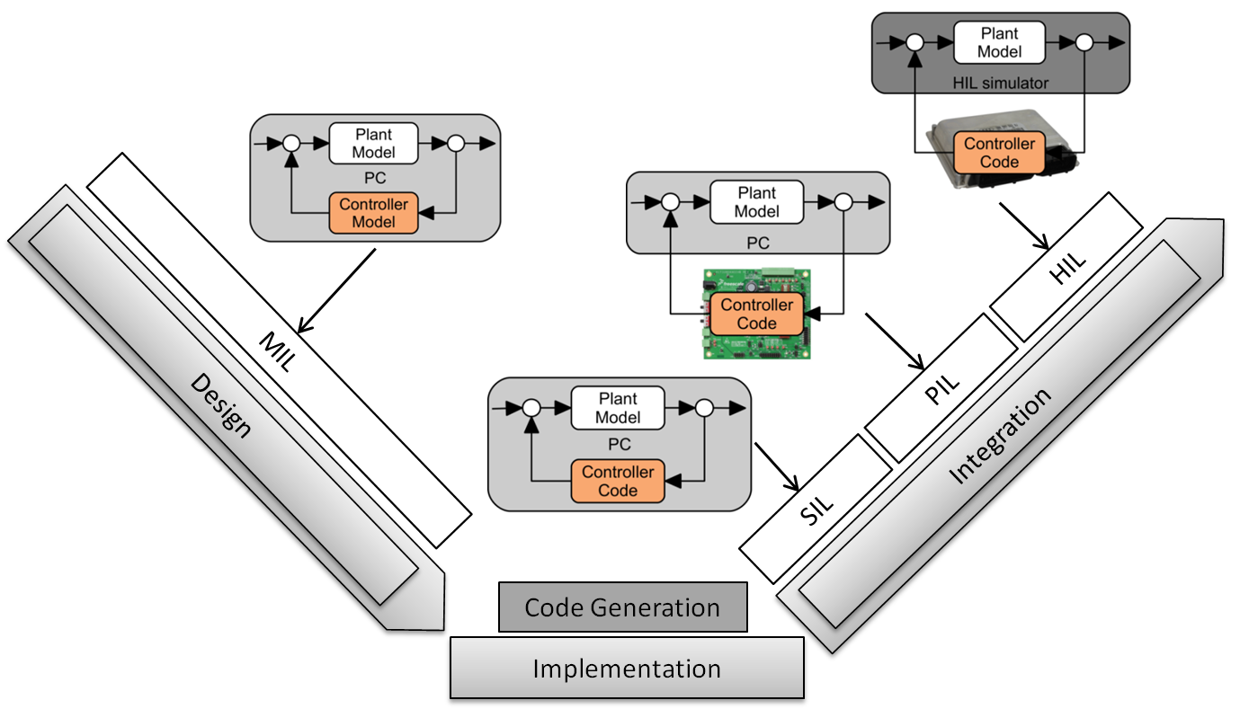
X-in-the-Loop Testing
The conventional model-based design and simulation based verification:
Simulation-based verification:
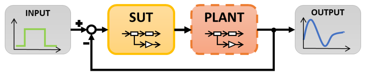
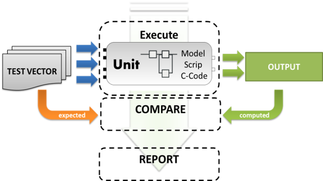
In the case of the mode 1, testing can be formulated in the form of a vector:
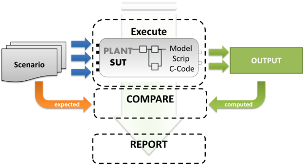
Closed-Loop Scenario Testing
Kaner defines scenario testing as the testing of a credible story that would happen in the real world
Open-Loop Unit Testing
Human-in-the-Loop Testing
Finally, flight tests with DLR‘s A320 pilots are performed on the Flight simulator.